


|
|
Raspy signals on the TS-870
My TS-870 dates back to 1996 and still performs very adequately. One of its best features -- thanks to DSP -- is the ability to vary the I.F. bandwidth in small steps to match the incoming signal and band conditions. Whether the mode is CW, FSK, SSB, AM or FM, it is very easy to reduce I.F. bandwidth to avoid adjacent channel interference, then widen the passband out again when conditions are clear. My transceiver has a couple of optional extras… the SO-2 temperature-compensated crystal oscillator (TCXO) and the DRU-3 digital recording unit. Installation was straightforward, using the notes in the Instruction Manual. Trouble on 15 metersOne of my favorite HF bands is 15 meters… so I was rather disturbed when an intermittent condition began to plague my TS-870 on 21 MHz. SSB signals would start to sound "raspy" and CW signals would change from a pure tone to a more spread-out signal, rather like auroral signals on VHF. One raspy station is not unusual, but when all the signals on a band start to sound rough, it is a sign of a receiver problem. Monitoring with a second transceiver showed the same effect was present on transmit, with my SSB signals sounding raspy and broad. An A-B receive test -- comparing signals heard on the second transceiver with reception on the misbehaving TS-870 -- highlighted the extent of the distortion. The 15 meter problem would usually clear up 20-30 minutes after switch-on. I put this down to thermal effects as the TS-870 warmed up. Further investigation showed that raspy signals were also present in the 17 meter band, 18.068-18.168 MHz. In fact, while the problem was present, it affected all received signals between 14.490 MHz and 21.489 MHz. Tuning beyond that range produced normal sounding SSB and T9 CW signals. This limited range of affected receive frequencies was the first clue. The TS-870 uses a first IF of 73.05 MHz and first local oscillator injection is provided by one of four separate VCOs (voltage controlled oscillators) to cover the full receive range of 30 kHz to 30.000 MHz. As shown in the table below, the third of these oscillators VCO3 (also known as VCO "C") is used to cover the range 14.490 - 21.489 MHz. This points the finger of suspicion at VCO3 - if this oscillator was producing a less than pure sine wave, it could make received and transmitted signals broad and raspy on 15m and 17 meters. First local oscillator frequencies
The next clue came from the "TS-850 repair page" on the web site of N6TR, http://n6tr.jzap.com. The article on "Raspy signals on some or all bands" suggests checking the LO2 VCO control voltage then readjusting trimmer capacitor TC1 on the PLL board until TP2 reads 5.0 volts. The TS-850 and TS-870 have very similar local oscillator frequencies, though they do not have identical PLL boards. I thought there might be enough similarity between the two radios to try a similar approach and the good news is -- it worked! If your TS-870 suffers like mine did, try the instructions below. Fix for TS-870 raspy signals on 18/21 MHzEquipment required: Phillips #0, #1 and #2 screwdrivers. You will need a 2 mm dia. Phillips #0 screwdriver for the VCO shield cover. Trimmer tool for preset capacitor. DC voltmeter. If you have the TS-870 Instruction Manual available, refer to page 76 then remove case and cover according to steps 1-3 of installing the SO-2 TCXO. If you do not have the Instruction Manual, proceed according to step 1 below.
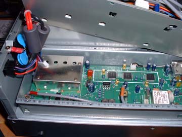
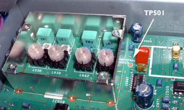
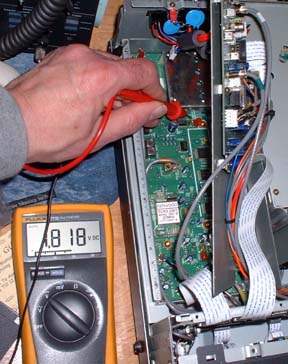
3. Locate the following items on the PLL circuit board. At the back of the transceiver is a metal box with a shield cover. The cover has four holes and is held in place with four miniature screws. The cover conceals the four VCOs, VCO1-4. Alongside the shorter edge of the metal box nearest the front of the transceiver is test point TP501 - the test point is an exposed copper pad on the etched circuit board.
4. Switch on power to the transceiver and set the controls as follows: Mode: FM, display frequency: 14.490 MHz. (You should hear relays opening/closing as you tune from 14.489 to 14.490 MHz). With the DC voltmeter, connect the negative lead to chassis ground and check the voltage at TP501 -- it should be 1.80 V plus or minus 0.03V. Adjust the display frequency by tuning upward toward 21.489 MHz - the voltage at TP501 should increase toward 4.5-7.0 V. In my case, the voltage at TP501 was 1.26V with the dial set to 14.490 MHz. This is a long way outside the specification of 1.80 V plus or minus 0.03 V and no doubt explained the raspiness. 5. If you discover a similar situation at the lower limit of your VCO3 range, proceed as follows. (However, if the voltage is exactly 1.8V then your problem lies elsewhere - possibly in one of the other VCOs. See later.)
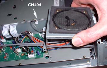
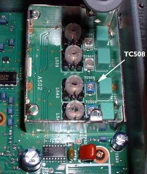
10. Disconnect the power, and reverse the disassembly procedure, reconnecting CN407, and replacing cover B. Replace the speaker assembly and reconnect CN404. Replace the top cover. 11. Reconnect DC power and check operation. There should be no sign of raspy signals at any point in the transceiver's warm up cycle. AfterthoughtsThe problem returns: Several weeks after the first adjustment, the problem began to return. Checking the voltage at TP501 showed that the VCO was drifting out of spec again. My solution was to readjust the VCO trimmer TC508, but this time choosing a different position for the rotor. A rotary trimmer can usually be adjusted to the same capacitance value at two different points in its 360 degree rotation -- so perhaps the first position had some 'hysteresis' and was slowly returning to its factory setting -- or it was simply intermittent in the first position. Trouble on other frequencies: If you find your TS-870 is producing raspy signals on a different set of frequencies, check the earlier table to see which of the four VCOs might be responsible, then adjust the appropriate trimmer under the shield cover -- TC506 is nearest the rear of the transceiver and TC509 is nearest the front. Check the other VCOs: While the covers are off, you might want to check the DC voltage at TP501 for the tuning ranges of all four VCOs. According to the service manual, they should all be adjusted to 1.80V at the lowest frequency of each range and change to 4.5-7.0V at the highest frequency. However, on the basis of "if it ain't broke, don't fix it" I would refrain from adjusting any of the other trimmers unless there are definite signs of trouble. Trouble on all frequencies: What should you do if signals sound raspy on all of the TS-870's frequencies? The advice from N6TR's site for the TS-850 was to check the control voltage for PLL2 . Translating to the TS-870, this VCO is inside a shielded compartment at the other end of the PLL board, nearest the transceiver front panel. According to the service manual, TP502 should indicate 5.0V +/- 0.03V and can be adjusted with trimmer TC1. I did not need to carry out this adjustment on my own TS-870, so I cannot share any experiences. - de NM9J, 11 Jan 2004, updated Feb 24 2004. |
|
G3VNQ-NM9J amateur radio site, 05-Jun-2007 |
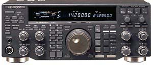 The Kenwood
TS-870 HF transceiver was introduced in 1995 as Kenwood's successor to the TS-850. Its
main claim to fame is the built-in digital signal processing for filtering and
detection at the final intermediate frequency (I.F.) -- as opposed to purely audio
frequency DSP.
The Kenwood
TS-870 HF transceiver was introduced in 1995 as Kenwood's successor to the TS-850. Its
main claim to fame is the built-in digital signal processing for filtering and
detection at the final intermediate frequency (I.F.) -- as opposed to purely audio
frequency DSP.