


|
|
|
Optional IF Filters for the Icom IC-706MkIIG
The standard IC-706MkIIG transceiver is equipped with a single 9MHz crystal filter for all the "BFO" modes – SSB, CW, and RTTY. This standard FL-272 filter has a bandwidth of 2.4 kHz at 6dB down, which is fine for SSB but inadequate for CW or RTTY on a crowded band. (There are separate filters for AM and FM.) Icom has five optional filters available for the IC-706MkIIG, with bandwidths of 250 Hz, 350 Hz, or 500 Hz for CW/RTTY and 1.9 kHz or 2.8 kHz for CW/RTTY/SSB. The transceiver can accommodate one or two of these optional filters, so your first puzzle is to decide which modes are most important, and whether you want narrow or wide selectivity. There is a table on page 23 of the Instruction Manual to help you choose. I ordered the 1.9 kHz FL-223 filter for narrow SSB work and the 350 Hz FL-232 for narrow CW and RTTY. Installation of the optional filters is quite easy – there is no soldering or special alignment involved. The only tool you will need is a Phillips #1 screwdriver. Instructions1) Switch off and disconnect all external cables, including the DC power cable. 2) Refer to the IC-706 MkIIG Instruction Manual page 59. Remove the five #1 countersunk Phillips screws from the top cover, then hinge the cover off, taking care with the speaker cable. If you cannot support the top cover safely, disconnect the speaker cable.
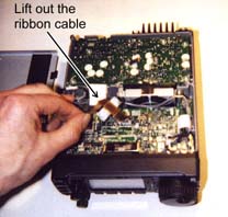
4) This step is not included in the Instruction Manual. You will see a ribbon cable, which crosses the standard IF filter. There is no need to disconnect this cable, just detach the adhesive tape securing the ribbon cable to the top of the filter. Make a note of how the ribbon cable runs behind the standard filter then gently pull the cable clear.
6) If you are installing a second filter, repeat the procedure in step 5. Make a note of which filter is installed in the Filter–1 position and which filter is installed in the Filter–2 position. 7) Return the ribbon cable to its original position. Reattach the adhesive tape to the top of the standard filter. 8) Replace the top cover, taking care with the speaker cable. Reconnect the DC power and antenna cables. 9) You will need to store the filter types in the transceiver’s memory. Refer to page 51 of the Instruction Manual for details. First, hold down the "Lock" button while turning the transceiver on with the "Power" button – this brings up the transceiver in "Initial set mode". 10) While in "Initial set mode", rotate the M-CH knob until you reach item number 9, "OPT. FIL 1". Rotate the main dial knob until the display changes from "no" to the filter you installed in the Filter–1 position. In my case, this was "FL-223". 11) If you installed a second filter, stay in "Initial set mode", rotate the M-CH knob until you reach number 10, "OPT. FIL 2". Once again, rotate the main dial until the display changes from "no" to the name of the filter you installed in the Filter–2 position. In my case, it was "FL-232". 12) To exit from "Initial set mode", turn power off by holding down the power button for two seconds, then turn power back on again. 13) Check operation of your new filters. Tune to an active band such as 14 MHz on mode USB or CW. Filter selection takes place from the "M3" menu. Push the "Display" button several times until the "M…" menu appears. Press the "Menu" button several times until "M3" appears. Filter selection is now controlled by the F-1 "FIL" button. One press of F-1 selects the narrow filter and "N" appears in the display. Holding down the F-1 "FIL" button for two seconds selects the wider filter (if available) and "W" appears in the display. See page 23 in the Instruction Manual for details. - de NM9J, March 10 2001.
|
|
G3VNQ-NM9J amateur radio site, 05-Jun-2007 |
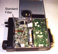 3) Inspect the
circuit board behind the front panel. You should see the standard IF filter that is
already installed and spaces for two additional filters. The spaces are labeled
"OPTION FILTER –1" and "OPTION FILTER –2".
3) Inspect the
circuit board behind the front panel. You should see the standard IF filter that is
already installed and spaces for two additional filters. The spaces are labeled
"OPTION FILTER –1" and "OPTION FILTER –2".
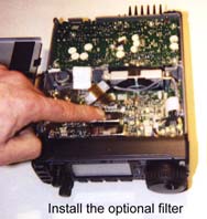 5) Remove the
optional filter (or filters) from their packing cases. Insert the first optional IF filter
into the holes on the circuit board. According to the Instruction Manual, the filter can
be installed in either direction – but for aesthetic reasons I preferred to align the
label with the one on the standard filter. The new filter will need a good push to seat it
firmly onto the circuit board.
5) Remove the
optional filter (or filters) from their packing cases. Insert the first optional IF filter
into the holes on the circuit board. According to the Instruction Manual, the filter can
be installed in either direction – but for aesthetic reasons I preferred to align the
label with the one on the standard filter. The new filter will need a good push to seat it
firmly onto the circuit board.