


|
|
|
Installing CR-282 High Stability Crystal Unit in Icom IC-706 MkIIG
The CR-282 is a replacement for the original reference oscillator crystal. According to the specifications, the standard IC-706 MkIIG transceiver can drift ±7 parts per million during the first hour of use. This corresponds to drifting ±1kHz at 144 MHz or ±3kHZ at 432MHz. These figures might be just acceptable for FM operation but distinctly unstable for any of the "BFO" modes — SSB, CW or RTTY. With the CR-282 installed the drift should be reduced to ±0.5ppm or ±72Hz at 144MHz, ±216Hz at 432MHz. Before you begin installation, tune in the standard frequency station WWV on 15.000 or
20.000 MHz to get a feel for the accuracy of the reference oscillator and how fast the
receiver changes frequency immediately after switch-on. Tune for approximate zero-beat in
the USB position, then change from USB to LSB while the station is transmitting a steady
audio tone. There should be no change in the audio frequency between USB and LSB when the
receiver is accurately tuned to the WWV carrier frequency. You will need the following tools: Phillips #1 screwdriver, small soldering iron, desoldering tool (RS 64-2098) or desoldering braid, small alignment tool for slotted coil slug core, diagonal cutters. 1) Switch off and disconnect all external cables, including the DC power cable.
Turn the transceiver over and take a look through the slot holes in the bottom cover
– you can just see the square reference oscillator unit in question at front- right. 2) Remove the five #1 countersunk Phillips screws from the bottom cover, then hinge the cover off. Remove the five screws from the top cover – hinge the top cover off, taking care with the speaker cable. If you cannot support the top cover safely, disconnect the speaker cable. (There are clearer diagrams in the Instruction Manual.)
4) Examine the PLL board -- you should be able to locate five Phillips screws holding the board in place. Four screws lie at the corners of the board, the fifth is in the middle, under the UT-106 DSP unit if fitted. 5) If the UT-106 DSP unit is installed above the PLL board, refer to the diagram on
page 61 of the Instruction Manual. Remove the ribbon cable from J3 on the DSP unit, then
maneuver the board out of the clips, far enough to see the central Phillips mounting screw
on the PLL board. Remove this central screw. 6) Remove the remaining four screws from the PLL board. Note that one screw has a star washer underneath. 7) Remove two ribbon cables from the connectors on the PLL board. See the diagram on page 60 of the IC-706 MkIIG Instruction manual for the location. Take care with these ribbon cables… you may want to wrap needle-nosed pliers with protective tape to pull out the cable gently and evenly.
9) On the PLL board, locate the two heat sink clips holding large semiconductor devices to the chassis. The clips are different sizes, so make a note as you remove them. 10) There is a shielded cable crossing the PLL board, which is held in a notch to the left of the fan. Push this cable out of the way so the PLL board can be removed. 11) With all the screws, cables and clips taken care of, lift out the PLL board very carefully. If you experience resistance, double-check that all five screws were removed and that the two shielded cables threaded through a hole to the other side of the chassis are not binding. "Hinge" the PLL board on its left edge so you have a clear view of the underside of the circuit board in the region of the reference oscillator. 12) Locate the solder lands where the two pins of the reference oscillator’s "existing crystal" are soldered to the underside of the PLL board. Use a miniature soldering iron and a desoldering tool or desoldering braid to suck out solder until the crystal can be removed. 13) Remove the Icom CR-282 High Stability Crystal Unit from its shipping carton and note the four mounting wires. If the wires were bent in the carton, straighten them with needle nosed pliers. Check the base of the CR-282 – you should see two of the mounting wires are marked with a quartz crystal symbol and the other two are marked with a resistor symbol, indicating the heating element.
When the CR-282 is aligned correctly, solder all four wires to the underside of the board with a miniature soldering iron. The ground connection may need more heat because of the thermal mass of the surrounding foil. Make quite sure that you have made good mechanical and electrical connections for all four wires and that solder is not touching any of the surrounding circuitry. Snip off the excess wire with diagonal cutters.
15) Reinstall the PLL board by reversing the procedure in steps 4-10. Remember to install the heat sink clips, shielded cable connectors, ribbon cables, DSP unit and five screws holding down the circuit board. Make sure the ribbon cables and coaxial plugs are snug in their sockets. 16) Before replacing the covers, re-connect the loudspeaker, antenna and 12 volt power lead. Turn on power and make sure the receiver is still functioning by listening to WWV. If the mode is set to USB or LSB, you should hear a rapid frequency shift in the first minute after switch-on as the new crystal unit warms up.
18) The next step is to adjust the reference oscillator for output on exactly 60.000000 MHz. If you have a high quality frequency counter, you can use the procedure in the Instruction Manual. Otherwise proceed to step 19. 19) Tune the receiver to WWV on the highest frequency where good reception is available (15.000.000 MHz or 20.000.000 MHz). First adjust L623 for approximately zero-beat with the WWV carrier. The receiver bandwidth and speaker response make it difficult to hear a true zero-beat, so use the technique of changing mode from USB to LSB and back again while adjusting L623 for the least difference in received audio pitch. This is most effective when WWV is transmitting a steady audio tone – there should be no difference in the tone frequency when switching between USB and LSB. 20) Bear in mind that the crystal unit will take around 1 hour to reach a steady temperature. Let the crystal unit and the transceiver warm up before making the last adjustment to L623. If you have another receiver or transceiver available, capable of receiving WWV on AM, you can make a very accurate final adjustment by listening for audible beats between the tone from the AM receiver and the tone from the IC-706 in USB or LSB mode. 21) Replace the bottom cover. - de NM9J, March 10, 2001, updated Nov 8, 2004. |
|
G3VNQ-NM9J amateur radio site, 05-Jun-2007 |
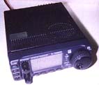 The Icom IC-706
MkIIG transceiver squeezes a lot of capability into a small box, and several of the
optional accessories are well worthwhile. Unfortunately, the Instruction Manual’s
section on "Optional Installations" is very lean, so here is a more meaty
description. (You should be familiar with soldering and unsoldering miniature components
on a circuit board before starting this job yourself. If you have any doubts, have Icom or
your Icom dealer install the unit. I won't be responsible for damage to your expensive
radio!)
The Icom IC-706
MkIIG transceiver squeezes a lot of capability into a small box, and several of the
optional accessories are well worthwhile. Unfortunately, the Instruction Manual’s
section on "Optional Installations" is very lean, so here is a more meaty
description. (You should be familiar with soldering and unsoldering miniature components
on a circuit board before starting this job yourself. If you have any doubts, have Icom or
your Icom dealer install the unit. I won't be responsible for damage to your expensive
radio!)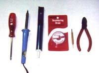
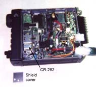
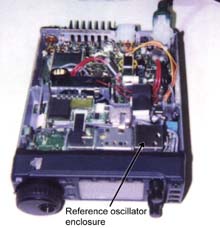 3) Inspect the
PLL unit, which is underneath the bottom cover. This circuit board is fastened to the
chassis, behind the front panel. Locate the square reference oscillator enclosure and
remove its shield cover, making a note of the hole location. Now you should be able to see
the reference oscillator’s "existing crystal", which is soldered to the PLL
board inside the reference oscillator enclosure.
3) Inspect the
PLL unit, which is underneath the bottom cover. This circuit board is fastened to the
chassis, behind the front panel. Locate the square reference oscillator enclosure and
remove its shield cover, making a note of the hole location. Now you should be able to see
the reference oscillator’s "existing crystal", which is soldered to the PLL
board inside the reference oscillator enclosure. 
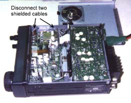 8) Now
for something not mentioned in the Instruction Manual. Locate the two shielded cables
which run from the PLL board through to the upper side of the IC-706 MkIIG chassis. These
cables are terminated with miniature coaxial connectors on the upper side. Label one of
the two connectors so you will be able to reinstall them both correctly in a later step,
then gently unplug both the coaxial connectors. Straighten out the cables so they are
ready to be pulled through the hole in the chassis.
8) Now
for something not mentioned in the Instruction Manual. Locate the two shielded cables
which run from the PLL board through to the upper side of the IC-706 MkIIG chassis. These
cables are terminated with miniature coaxial connectors on the upper side. Label one of
the two connectors so you will be able to reinstall them both correctly in a later step,
then gently unplug both the coaxial connectors. Straighten out the cables so they are
ready to be pulled through the hole in the chassis.
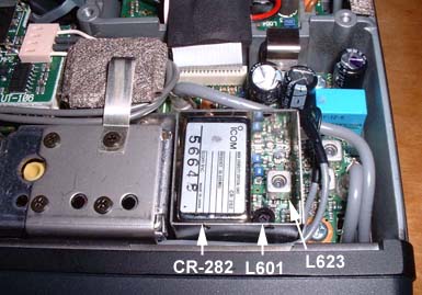
 17) Replace the
IC-706 top cover and turn the transceiver over so you have easy access to the PLL board.
Note the position of inductor L601 (see photo above and diagram, page 60 of the
Instruction Manual), and make sure your alignment tool is small enough to fit the slot in
the inductor’s core. Before starting adjustments, replace the shield cover over the
reference oscillator enclosure. Be sure that the holes in the cover align with the
variable inductors.
17) Replace the
IC-706 top cover and turn the transceiver over so you have easy access to the PLL board.
Note the position of inductor L601 (see photo above and diagram, page 60 of the
Instruction Manual), and make sure your alignment tool is small enough to fit the slot in
the inductor’s core. Before starting adjustments, replace the shield cover over the
reference oscillator enclosure. Be sure that the holes in the cover align with the
variable inductors.